The Making of an AGI Background Picture
By Juha Terho
Note: This tutorial contains information that has become somewhat obsolete since there exist AGI editors that are newer than PICEDIT. This tutorial will not be updated. However, this page will not be removed, either. I will retain it here for posterity – and because of its potential usefulness for people interested in AGI game creation. Most of the methods demonstrated here can be used with any AGI editing software. In addition, I want to preserve a bit of history of how I created a background picture for my own AGI game, AGI Quest I. This page was originally created in February 1998.
As I wrote in the (limitations of priority bands and some workarounds), priority bands impose some restrictions on room design. You often must take the bands’ position on the AGI playing screen into account when planning the placement of background features. On this page, I’ll show a simple trick that can simplify this process a great deal.
In this text, I will use Lance Ewing’s PICEDIT as the picture editor. This is simply because there are no other AGI picture editing packages available as of this writing, with the exception of the Russian AGDS editor. If you don’t speak Russian (я не говорю по-русски), using the AGDS editor is about as easy as creating picture resources with a hex editor. So Lance’s program is pretty much all you have right now – but don’t worry, it’s easy to use. So let’s get started.
Obviously, it would help if you knew where the priority bands are when you’re drawing. Although PICEDIT shows the number of the current priority band on the status bar when you move the mouse around, this isn’t really helpful as you don’t get to actually see the bands.
Luckily, PICEDIT has a &qout;picture tracing&qout; option. It allows you to specify a bitmap graphics file to be displayed on the screen when you’re drawing. This means that you can import a drawing or a photograph on &qout;top&qout; of which you can draw the actual PICTURE resource, using the imported image as a guide. If all this sounds a bit confusing, don’t worry, there’s a real-life example coming up in a moment.
First, let’s look at how &qout;tracing&qout; can be used to show the priority bands onscreen. Here’s a file that you can download and use with PICEDIT:
- pribands.pcx (3 kB, courtesy of Peter Kelly)
PICEDIT is designed to take a PCX file with 256 colors and dimensions of 320 × 168 pixels and display it on the drawing screen when the user wants to. To use this feature, you must start PICEDIT with the command picedit filename.pcx. In this case, the command you’ll want to use is picedit pribands.pcx, of course.
Note: When you start PICEDIT like this, the program may take up to 10 seconds on slower machines to start. Be patient...
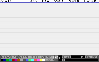
In PICEDIT, F10 will toggle the PCX on and off. This is how Peter’s pribands.pcx will look in the editor:
You can now see the priority bands onscreen as vertical lines, which will be handy when placing objects on the background.
An important point to note, however, is that the image you load using this feature will in no way affect the actual PICTURE resource. The purpose is not to import existing images and convert them to PICTURE resources (after all, that would be practically impossible) but to make the artist’s job easier by giving him the possibility to draw on top of an existing image – which in this case happens to be a picture of the priority bands.
Now, most people, including me, feel more comfortable drawing with pen and paper instead of a mouse. This is what PICEDIT’s tracing function was really designed for: you can design the room on paper, transfer the drawing to your computer using a scanner, load it in PICEDIT and draw on top of that.
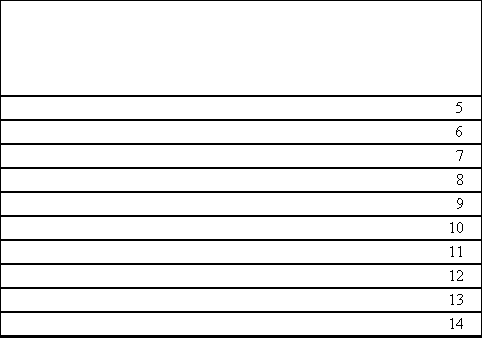
However, when you’re drawing on paper, you have no idea of where the priority bands are, so proper object placement on the screen becomes guesswork. Here’s a simple solution – similar to the one above – that I came up with:
(The priority band numbers aren’t really necessary but are included anyway.)
The idea is to print out the above picture on paper, design the picture on that, scan it back into the computer and &qout;trace&qout; over it in PICEDIT. Here are step-by-step instructions:
- Save the above picture on your hard drive and load it in a paint program. I use Paint Shop Pro in Windows 95.
- Print it out. If possible, have the program stretch the image to fit the entire page. Paint Shop Pro allows this.
- Design the background on the paper. Use the priority band lines in the picture to plan the placement of background features (see the limitations of priority bands and some workarounds for this.)
- Use a scanner to transfer the drawing to your computer.
- Resize the picture to 320 × 168 and decrease its color depth to 256 colors (Paint Shop Pro is really good for this). The picture’s proportions will be stretched horizontally somewhat because of aspect ratio differences. Ignore this, as the image will stretch back to normal in the picture editor and in the finished game.
- Save the image as a PCX (select Version 5 as the sub-type if you’re using Paint Shop Pro) and load it in PICEDIT (
picedit filename.pcx). If you’re using Windows 95, you can also drag-and-drop the PCX file onto PICEDIT.EXE. - You can now draw the background using your pencil drawing as a guide. The background is off by default when you start PICEDIT, so press F10 once to activate it.
If you’re not sure what all this means, the real-life example I promised above is coming up now.
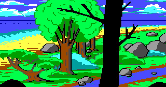
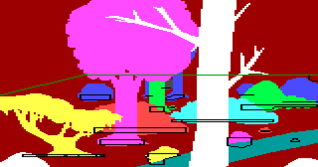
I’m working on a small game, AGI Quest I [note: completed June 2003]. It won’t be a real game as the finished version will only have four rooms and no real plot to speak of. The point is just to have a graphics/animation test with some objects and events. I’ve been designing the rooms on paper using the priority band guide above. Here’s the first room I’ve completed – visual screen on top, priority screen on bottom:
As you can see, it’s a King’s Quest-esque scene with an ocean, some trees and a stream. I’ll now explain briefly how I created it using the methods I described above.
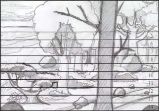
I started by printing out the priority band guide on paper and designing the room on that with a pencil. I then scanned it to my computer using a flatbed scanner. The result:
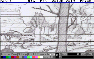
I resized this image to 320 × 168, dropped its color depth to 256 colors, saved it as a PCX and loaded it in PICEDIT:
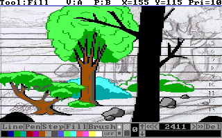
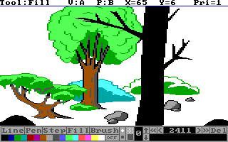
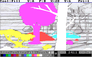
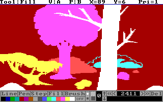
Then I simply started drawing. Here’s a work-in-progress shot of the visual screen with the background tracing option turned on and off (with F10).
The same with the priority screen:
You can download the finished PICTURE resource if you want to study it:
- picture.2 (7 kB)
To try walking around the scene, simply add it to Peter Kelly's template game as PICTURE.2.
A slightly updated version of the picture can be found in AGI Quest.
Some comments, in no particular order:
- If you compare my original pencil drawing with the finished picture, you’ll notice that the trees in the upper right hand corner are gone. I was unhappy with the way the trees looked, so I improvised new background features in their place.
- When you use scanned drawings in PICEDIT that have been drawn on top of a priority band guide, keep in mind that the priority lines in the scanned image might be one pixel off because of the scanning, cropping and resizing involved. This shouldn’t be a big problem, though, just something to watch out for, especially when drawing the control lines.
- In this room, there are some areas where characters will appear on the wrong side of background objects. In my game, I intend to correct these errors with the
set.prioritytrick explained in the previous tutorial. - The green control line that runs vertically across the screen will trigger a room change in the final game. Areas above this control line can’t be accessed by the player. This is why the rocks above the line and the ocean don’t show up on the priority screen in any way – they aren’t a part of the playing area, just background details.
